Machinery / Semiconductors and Automation
Other Inspection Systems
Iwatani offers advanced one-stop solutions that encompass all processes encountered in the semiconductor manufacturing sector.
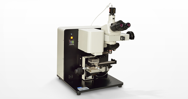
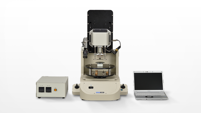
Scratch Tester
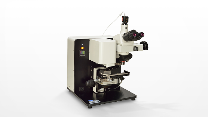
Measures Adhesive Strength of Thin Films of Several Micrometers or Less
Film thicknesses for the micro-scratch method (JIS R 3255 and JIS K 7376 compliant) are several micrometers or less. This approach, a refinement of the scratch method used to evaluate the adhesive strength of thin films formed on material surfaces and the base material, detects peeling in the thin film. The device evaluates the adhesive strength of ultrathin films. In addition to the micro-scratch method designed to detect fractures in such thin films, it incorporates a high-sensitivity fracture detection mechanism based on technologies (patented by the manufacturer; Patent No. 5070146) for evaluating the adhesive strength of ultrathin films.
Features
- Evaluates adhesive strength of ultrathin films of several micrometers or less thickness. *A film thickness of 10 nanometers has been measured.
- Samples can be heated and evaluated in heated environments.
- Measuring of lens curvature
- Time-series friction force histogram (TSFH) analysis allows evaluations of friction coefficients in the 100 μm × 100 μm region
Applications
- DLC
- Optical thin films
- Metal films
- PET films
- Functional thin films (AR, RF)
- Electrode membranes, etc.
Specifications
| Load Detection Mechanism | Load Application Range | 1 to 1,500 mN |
|---|---|---|
| Load Resolution | 0.3 mN | |
| Allowable Overloading | 300% FS | |
| Signal Output in Horizontal Axis | Detection Signal | Speed signals |
| Frequency Range | 20 Hz to 10 kHz | |
| Excitation Frequency | 45 Hz | |
| Excitation Amplitude | 0, 5, 10, 20, 40, 50, 80, 100 μm | |
| Signal Output in Vertical Axis | Detection Signal | Acceleration signals *Patented technology |
| Frequency Range | 20 Hz to 10 kHz | |
| Stylus | Material and Configuration | Diamond (R5, 10, 15, 25, 50, 100 µm) |
| Sapphire (R250, 500 μm) | ||
| φ3/32 inch ball can be mounted | ||
| Z Axis Drive Mechanism | Drive System | Stepping motor drive |
| Load Application Axis | Drive Range | 20 mm (Coarse movement range of +30 mm manually) |
| Drive Resolution | 0.5 μm | |
| Drive Speed (During Measurement) | 0.1 to 10 μm/s | |
| Drive Speed (During Preparation) | 1 mm/s | |
| X Axis Drive Mechanism | Drive System | Stepping motor drive |
| Scratch Direction | Drive Range | 20 mm |
| Drive Resolution | 0.5 μm | |
| Drive Speed (During Measurement) | 0 to 20 μm/s | |
| Drive Speed (During Preparation) | 1 mm/s | |
| XY Axis Drive Mechanism on Table for Samples | Drive System | Manual drive with a micrometer |
| Drive Range | ±6.5 mm | |
| Data Output Method | USB | |
| Dimensions and Weight |
|
|
| Power Supply | 100 to 240 V AC | |
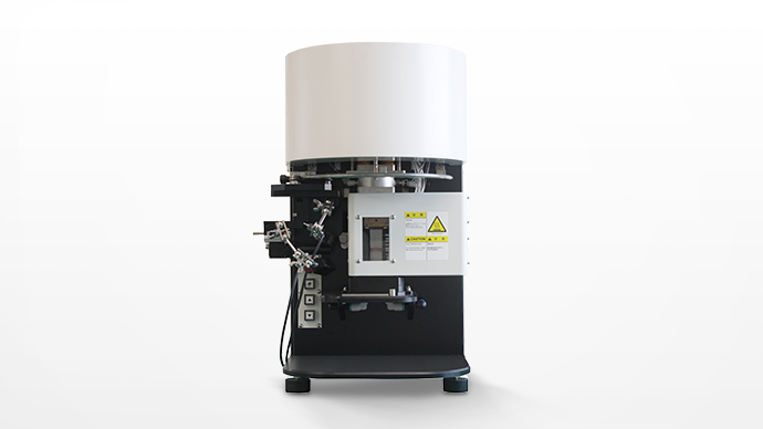
Friction and Wear Tester
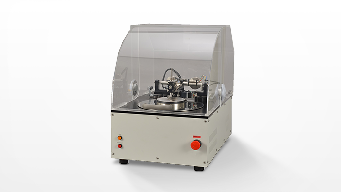
Evaluates Wear Resistance Based on Changes in Friction Coefficient.
This device measures the coefficient of friction by the pin-on-disk testing method. Measuring the coefficient of dynamic friction (slipperiness) fractures the surface and changes the coefficient of dynamic friction. This friction and wear tester is designed to identify very small surface fractures and peeling of thin films and coating materials as changes in the coefficient of dynamic friction and to quantify wear resistance by identifying the point at which the coefficient of dynamic friction changes and determining the number of slides that generate significant surface wear.
Features
- Evaluates wear resistance due to changes in coefficient of dynamic friction based on surface changes caused by wear (shaving, roughness, peeling)
- Light-load measurement and evaluation of coefficient of friction without scratching surfaces
- Measurement in various environment modes (measurement at high temperature, varied humidity, in liquid, simultaneous measurement of electrical contact resistance)
- Measurement in various drive modes (rotation, circular reciprocating sliding, spiral, linear reciprocating sliding, unidirectional linear drive)
Specifications
| Load Mechanism | Load Method | Actual load method by weight (dead weight) |
|---|---|---|
| Load | 50 to 3,000 g | |
| Zero-Adjustment Mechanism | Gimbal type (manual adjustment with counterweights) | |
| Friction Force Detection Mechanism | Friction Force Detection | 0.25 to 5,000 g |
| Resolution | 1/20,000 | |
| Stage Drive Mechanism | Rotation Speed | 0.1 to 600 rpm (rotation measurement) |
| 0.1 to 24 rpm (reciprocating sliding measurement at the circumference) | ||
| Measured Radius | 1 to 50 mm | |
| Measured Line Speed | 0.01 to 3,141 mm/s | |
| Sampling Setting | Select from 1 ms, 10 ms, 50 ms, 100 ms, 500 ms, 1 s, 5 s, 10 s, 30 s. | |
| Safety Functions | Emergency stop button, cover opening/closing detection | |
| Data Output Method | USB | |
| Dimensions and Weight |
|
|
| Power Supply | 100 V AC, 7 A (with heating option) | |
| Heating Temperature Range (Optional) |
RT to 200℃ (dry) | |
| RT to 130℃ (wet) *Combined with solution cell |
||
| Temperature Accuracy | ±2℃ | |
| Linear Reciprocating Sliding Measurement Unit (Optional) |
Reciprocating Width | 1 to 30 mm |
| Reciprocating Rate | 0.1 to 200 times/min | |
| Heating Temperature Range | RT to 200℃ | |
| Temperature Accuracy | ±2℃ | |
| Humidification Control Unit (Optional) |
Humidification Range | 20% to 80% RH *Requires preparation of low humidity environment |
| Temperature Range | Room temperature | |
| Temperature Detection Accuracy | ±0.5℃ | |
| Humidity Detection Accuracy | ±5% RH | |
Sliding Peel Strength Tester
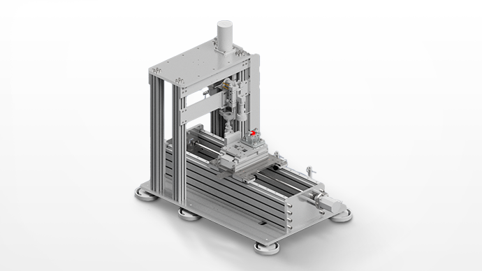
Evaluates Interface Fractures Due to Fatigue Wear Based on Number of Slides and Applied Loads
Methods such as scratch testing and friction wear testing are used to test the interface strength (adhesion) of coatings. In scratch testing, deformation of the sample surface due to the applied load has effects beyond frictional forces acting laterally on the coated surface. This means incremental load tests are ineffective in evaluating the sliding durability of a coating with a low coefficient of friction. The friction and wear test is a durability evaluation method better suited to real-world conditions than the scratch test. However, selecting test conditions and measurements take considerable time due to the number of slides required to generate a fracture, depending on the applied load selected. The sliding peel strength tester is capable of testing by ramping up the load, and has drawn attention as a method for evaluating the interfacial strength of hard films, including DLC.
Features
- Evaluates interface fractures caused by fatigue wear from load and sliding (fracture modes differ from sample to sample)
- Automatic image capture of sample and ball during friction test (with ball detached from the sample)
- Detects fluctuations in the friction coefficient, and stops the test upon fracture occurrence
- Various safety functions enable automatic driving day and night
Specifications
| Load Application Mechanism | Drive Range | 50 mm |
|---|---|---|
| Drive Control (During Measurement) | Feedback based on load control | |
| Applied Load Range | Max 2,000 N | |
| Load Accuracy | 1% or 5 N of applied load, whichever is greater | |
| Sliding Mechanism Θ Direction |
Sliding Distance (Total Width) | 1 to 10 mm (manual setting) |
| Drive Frequency | Max 50 Hz (sliding distance: 2 mm or less) | |
| Max 5 Hz (sliding distance: 3 to 10 mm) | ||
| Moving Mechanism X Axis |
Drive Range | 500 mm |
| Additional Wear Mark Measuring Instrument | Please contact us. | |
| Wear Marks Tracking Mechanism | Autofocus Range | 2 mm |
| Sample Observation | 0.75 mm × 0.95 mm (Resolution: 5M color CMOS) |
|
| Indenter Observations | 1.0 mm × 1.3 mm (Resolution: 5M color CMOS) |
|
| Data Output Method | USB | |
| Dimensions and Weight |
|
|
| Power Supply | AC 1,500 VA (main unit) 500 VA (humidification optional) |
|
| Friction Force Detection Mechanism | Detection Range | Max 2,000 N |
| Detection Accuracy | ±0.5% FS | |
| Environmental Control Mechanism | Hot Plate Heating Range | RT to max 200℃ (temperatures in sample table) |
| Humidity Detection Range | 20% to 80% RH (Mixed airflow method) |
|
Tacking Tester
Quantifies Adhesive Strength Based on Fingertip Assessment
Subjective evaluations of tackiness can result in significant errors traceable to subjective differences in judging the instantaneous adhesive force of various pastes and adhesive tapes. This device allows quantitative evaluation measurements. A controlled (entry speed, pressurizing force, pressurizing time, traction speed) measuring probe is pressed against the sample and the adhesive force during the pulling process is measured.
Features
- Four types of pressure patterns and two types of pressing methods allow real-world evaluations
- The heating method allows calculation of the temperature dependency of adhesive strength (samples and stages can be heated)
- Evaluates adhesive strength by graphing measurement data and evaluating integrated values
- Allows measurements in various environments (atmosphere control, UV irradiation)
- We offer a service for optimizing the probe for the actual process (material and shape need specifying)
- Meets domestic and overseas test standards (IIW SC/IA-SP058, IPC J STD-005, AST M 2979).
Applications
- Evaluation of pain associated with peeling off cataplasms (e.g., poultice)
- Setting conditions for picking up dies from dicing tape
- Simulation of capture by continuous pressurization of insect catching material
- Simulation of toner-fixing unit for copier (toner release, fixability, gloss measurement sample preparation)
Specifications
| Measurement Method | Pressing/pulling Two-step test | |
|---|---|---|
| Measuring Speed | Pulling | 0.001 to 15 mm/s |
| Pressing | 0.001 to 5 mm/s | |
| Drive Range | X Axis | ±50 mm (motor-driven) |
| Y Axis | ±50 mm (motor-driven) | |
| Z Axis | Max 70 mm (motor-driven) | |
| Stage Heating Range | 50-mm square (optional) | |
| Stage Temperature Range | Heating Stage | RT to 250℃ ±3℃ |
| Cooling Unit | -20℃ to RT | |
| Heating/Cooling Stage | 5 to 100℃ ±3℃ | |
| Probe Heating Temperature | RT to 200℃ ±3℃ (optional) | |
| Pressing Control Method | Load control, push-in amount control, stop after push-in | |
| Probe | Standard φ5.0 mm made of SUS (φ2.0 mm, φ5.1 mm, φ10.0 mm; optional) |
|
| Measurement Accuracy | ±0.2% FS | |
| Sensor Loading | Select from 500 g, 1 kg, 2 kg, 5 kg, 10 kg, 20 kg, 30 kg FS (Pressurization range: 0.5% to 80% FS) |
|
| Autozero Function | Available (Automatic zero-adjustment for each measurement) |
|
| Sensor Calibration Function | Automatic registration | |
| Output Unit | gf, N (mN) switching display | |
| Pressing Time Setting | OFF or 0.01 to 3,600 s; 0.01 s unit setting | |
| Sampling Interval | Select from 1, 10, 50, 100, 500, 1,000, 2,000, 4,000, 8,000 Hz | |
| External Output | USB | |
| Input Power Supply | 100 to 240 V AC, ±10%; 50/60 Hz | |
| Power Consumption | 300 VA | |
| Dimensions and Weight |
|
|
| Safety Function | Overload | Stops automatically if measured values exceed measurement range during measurement |
| Detection Function | ||
| At the Time of Probe Falling | Halts immediately when the measuring probe touches sample | |
| Damage Prevention Function | ||
| Overheating | Heating halted when heating temperature exceeds certain limit | |
| Protection Mechanism | ||
Thermal Conductivity Measurement System
Measures Thermal Conductivity of Conductive Adhesives and Conductive Pastes For Assessing Effects of Heat Dissipation
As mobile devices and other devices grow smaller and thinner, printed circuit boards have also become increasingly thinner, multi-layered, and modularized. The need has emerged to mount electronic devices that are sensitive to high temperature in low temperature environments. However, the move to lead-free solder has made high-melting-point solder unavoidable. Given the importance of the heat dissipation effects of alternative conductive adhesives, the need for a test device for evaluating thermal conductivity has emerged. We offer cost-effective equipment capable of measuring thin layers and high thermal conductivity materials.
Features
- Enables quality control for conductive adhesives, heat-dissipating conductive pastes, heat-dissipating film sheets, resin materials, etc.
- Thermal conductivity of laminated devices can be evaluated
- Can be measured as the test piece alone or with the material joined
- Can measure test pieces with thickness of 0.05 to 20 mm
- Incorporates three measurement modes: manual input, motor pulse signal, and camera measurement (optional) for measuring sample thickness
- Using samples of different thicknesses enables measurement of thermal conductivity excluding interfacial thermal resistance
- Allows wide-ranging thermal conductivity measurements using rods of different materials
Specifications
| Sample Configuration | Face Shape | 20-mm square or 10-mm diameter - common |
|---|---|---|
| Thickness | Min 0.05 mm to Max 20.0 mm | |
| Standard | JIS H 7903, ASTM D5470 compliant | |
| Laws and Regulations | RoHS Directive | |
| Measurement Accuracy (Thermal Conductivity) | Difference From the Nominal Value | ±10% (Standard sample SUS304) |
| Measurement Range | 0.01 to 150.00 W/m・K | |
| Temperature Setting Range | Heating Block | RT to 200℃ |
| Test Pieces | RT to 120℃ | |
| Temperature Control | Heating | PID control or constant power control |
| Cooling | Water cooling (cooling block temperature: 5℃ to RT) | |
| Weight Setting Range | 10 to 1,000 N | |
| Communication | PC | USB 2.0 compliant |
| Data Collection Function (With CSV File Export) | Temperature at each measuring point | |
| Thermal conductivity/thermal resistance *Display can be switched | ||
| Option | Chiller | Cooling block temperature: 0℃ to RT |
| Camera for measuring thickness *Lens required depends on sample thickness |
||
| Safety Function | Overheat prevention alarm | |
| Overload prevention alarm | ||
| Safety cover, solenoid lock | ||
| Equipped with a ground-fault circuit breaker | ||
| Cooling abnormality detection | ||
| Power Supply | 100 V ±10% 50/60 Hz | |
| Dimensions and Weight |
|
|
Please inquire for more information on other inspection systems.
Electronics Equipment Department
Tokyo
81-3-5405-5781
Osaka
81-6-7637-3072